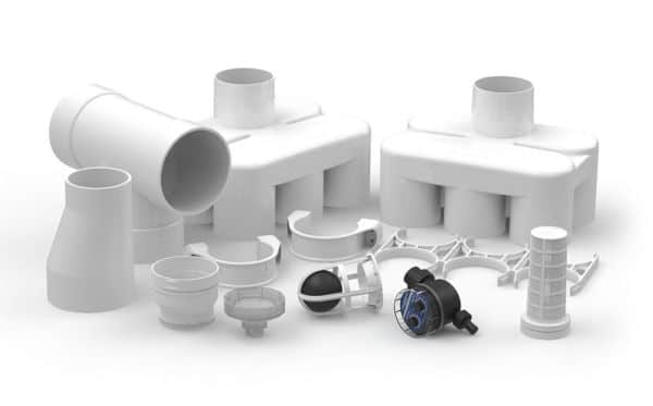
Rain Harvesting First Flush Commercial
The Delta Commercial is available to suit 150mm and 225mm downpipes. Allowing you to enjoy the easy install benefits of using 100mm pipes for the first flush chamber. For larger volumes, consider the Delta manifold installation options.
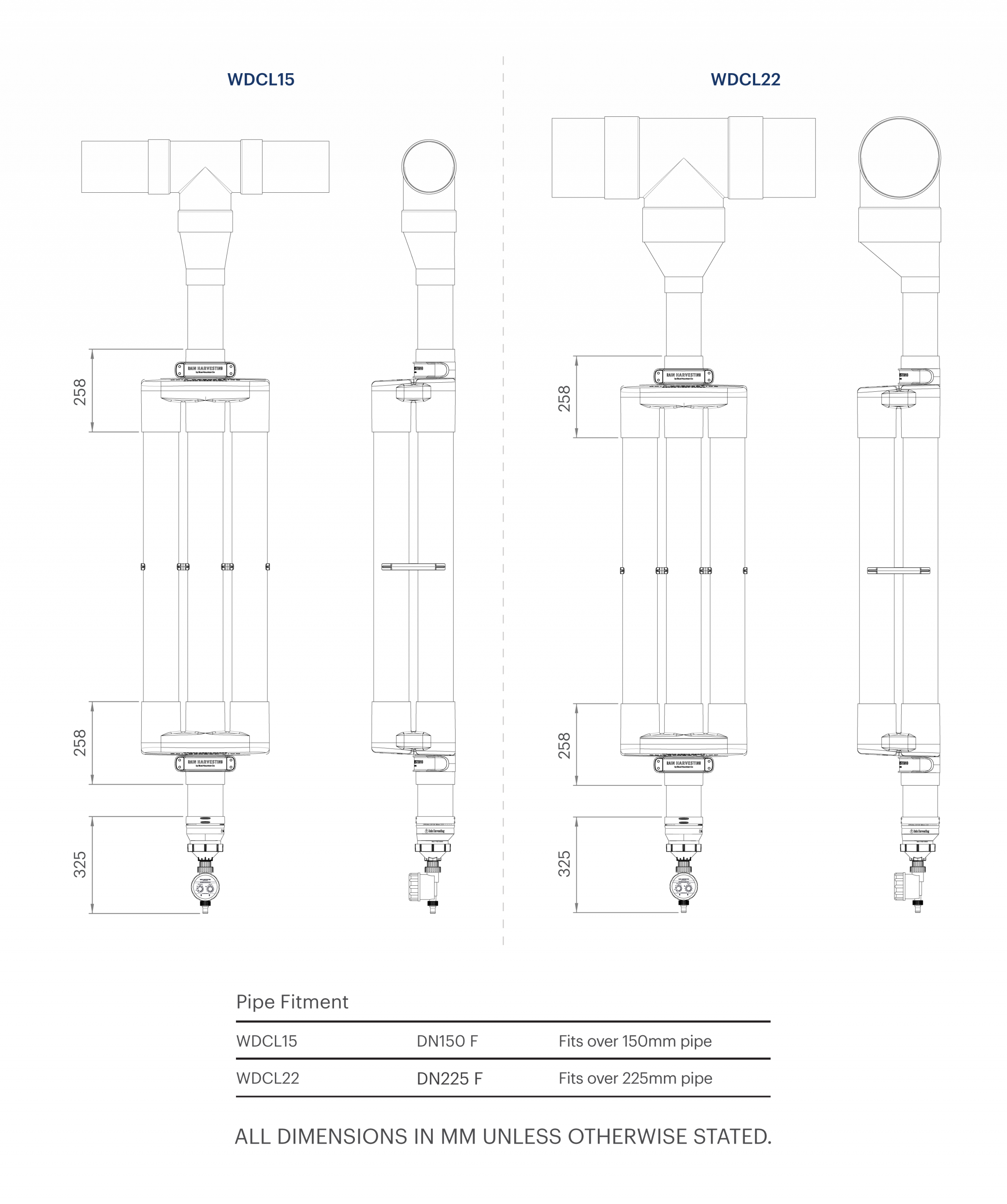
WDCL15 | 150mm
WDCL22| 225mm
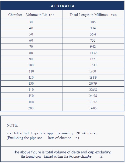
Easily divert large volumes of first flush with the Delta High Volume Chamber. Using multiple 100mm pipes to create the diversion chamber, the Delta’s revolutionary design makes installation simple. The Delta chamber is customizable up to 2 metres. Every 1m of Delta chamber = 73 litres of diversion.
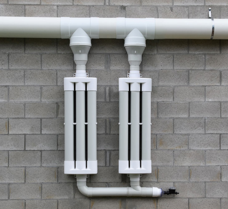
For larger volumes, consider the Delta manifold installation configurations.
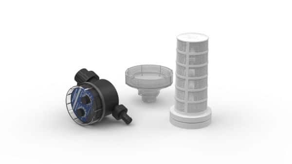
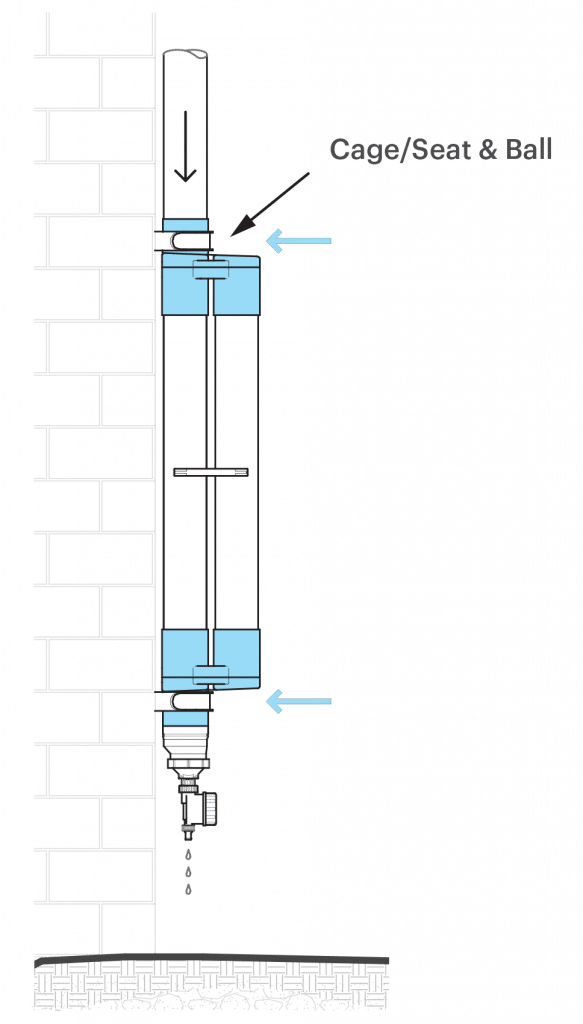
Integrated ball and seat
This unique design ensure that the first flush ball remains close to the seat, even in high flow events, ensuring the diverter seals as soon as the chamber is full. No more lost balls when cleaning your outlet either!
Divert larger volumes
By allowing you to determine the frequency of first flush, the Advanced Release Valve ensures that the Delta’s first flush diversion is optimized. The transparent, rapid release exit funnel reduces build up and blockages while allowing for easy
Installation Guide
- It is a requirement to install a rain head upstream of any downpipe feeding the Delta Commecial First Flush. Large debris must not enter the First Flush chambers to prevent blockages and damage to the Advanced Release Valve.
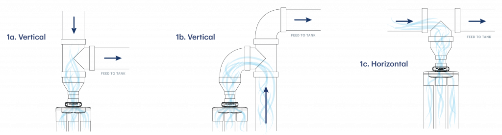
- Select an installation point for your Delta Commercial First Flush unit/units. Your diverter chamber must be installed vertically when using the supplied Wall Brackets. Consider the location of the 150mm/225mm Tee Junction/s in your Rain Harvesting line and the space required for your assembled Delta Chamber/s. The Tee Junctions can be installed in the horizontal or vertical orientation to suit your installation.NOTE: Some vertical tee installations may require extra 150mm/225mm fittings depending on project requirements (see Figure 1 for suggested installation locations).The outlet and Advanced Release Valve must also be accessible for maintenance and inspection.
- Remove Delta components from packaging and lay out parts ready for assembly.
- Using one of your Post/Wall brackets, screw the lower bracket to the wall at your chosen installation point. The outlet of your Advanced Release Valve must sit at least 150mm (6″) from the ground when fully assembled, so when combining multiple flush points in a manifold setup, secure your lower bracket approx. 900mm (35”) above the ground. Ensure your first Post/Wall bracket is positioned to allow room for your other Delta chambers.
- Determine chamber length using the calculation chart provided, based on your Rain Harvesting roof collection area and considered pollution level (see Delta Diversion Chamber Calculator Tab below).
- Using a tape measure, mark, cut and deburr 6 equal lengths of 100mm (4”) pipe to be used as the Chamber Pipes.NOTE: It is critical that all the Chamber Pipes are exactly equal length. It is also recommended to apply a small chamfer to the outside ends of the 6 Chamber Pipes to improve ease of insertion into the Chamber Sockets.
- Using priming fluid, clean all internal sockets of both Delta End Caps and each external end of the six Chamber Pipes.
- Working with one Delta End Cap, apply solvent weld glue internally to a Chamber Socket and then externally to one of the Chamber Pipes. Bring the two together ensuring the pipe is inserted fully into the socket and hold until firm. Repeat this step for all remaining pipes until all six Chamber Pipes are glued into one Delta End Cap.NOTE: Refer to solvent weld glue manufacturers specifications and curing times. All sockets of the Delta End Cap are stepped internally. The inner socket is for use with 100mm UPVC pipe and the outer socket for 4” SCH40 pipe. Only apply solvent weld glue to the socket relating to the pipe in use.
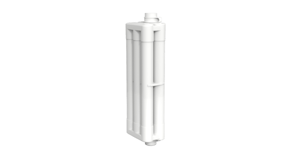
- Slide the Chamber Support Spacer over the open end of the Chamber Pipes and position approx. 200mm (8”) from the unglued end.
- Before completing the next step consider the installation position of your Delta and how the inlet and outlet should be oriented (Figure 2 – Delta Post/Wall – Inlet/Outlet Positions)
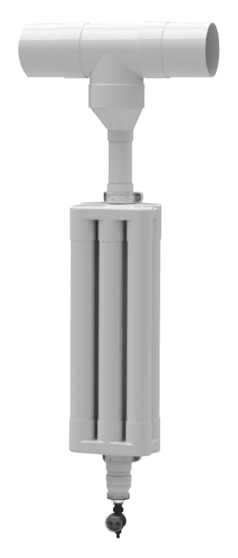
- Working quickly, apply solvent weld glue to each of the six internal Chamber Sockets of the remaining Delta End Cap and then externally to the six Chamber Pipes. Quickly bring the Delta End Cap together with the six pipes by first aligning three pipes and sockets on one side and then rolling onto the remaining three pipes. Using some force, push the Delta End Cap down onto the Chamber Pipes ensuring the pipes enter the socket fully and hold in position until secure (Figure 3 – Delta Diagram).NOTE: Refer to solvent weld glue manufacturers specifications and curing times.
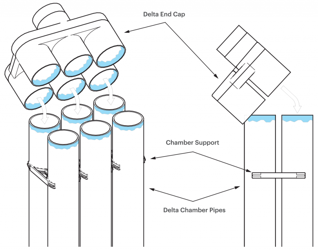
- Move the Chamber Support Spacer down the Chamber Pipes to approximately the half way position ensuring the pipes will be supported evenly.
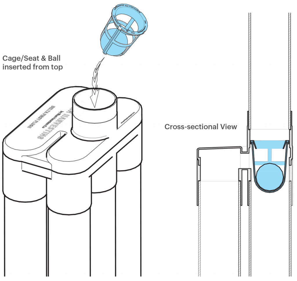
- Insert Cage/Seat & Ball into the inlet (upstream) Delta End Cap, ensuring it is oriented correctly then snap into position (Figure 4).
- Place your assembled Delta in the Post/Wall Bracket and support the chamber as you fit your upper bracket around the inlet on the upper Delta End Cap and screw it to the wall or post.CAUTION: Failure to support the unit in the upright position while attaching the upper bracket could crack the bottom Chamber End Cap.
- Measure your existing 150mm/225mm tank feed pipe and cut to create space for the appropriately sized Tee Junction. Ensure all cut edges are clean and smooth then use priming fluid to clean all external pipe ends and internal sockets of the Tee Junction.
- Install the Tee Junction and Tapered Reducer onto the existing pipe and extend the branch line below the Tapered Reducer with 100mm (4”) pipe to the inlet of the upper Delta End Cap using solvent weld glue.NOTE: Ensure the Tapered Reducer is orientated correctly to suit your installation e.g. so that the back of the 100mm socket/pipe is flush against the wall to align with the inlet of the Delta End Cap.
- Repeat steps above for any additional chambers in the manifold system.
- If you have chosen to utilise multiple flush points with your Delta Manifold installation skip to Step 20. If you have chosen a single flush point with your Delta Manifold installation, use a 90° bend for one of the chamber outlets and additional 90° junctions for each additional chamber, connect the outlets of the Delta End Caps together using 100mm UPVC pipe and solvent weld glue ensuring to allow minimum fall of 1 in 100 (1%) to the open end.
- Using solvent weld glue and a 120mm piece of 100mm UPVC pipe, attach the 100mm-90mm (4”-3”) Socket Reducer to the open end. Insert the Primary Filter Screen into the Socket Reducer and screw the Transparent Rapid Release Exit Funnel onto the threaded end of the Socket Reducer (see Figure 5).
- For multiple flush points complete the following steps for each Delta chamber. Use a minimum of 170mm of 100mm pipe (3.7” of 4”) and solvent weld glue, attach the 100mm-90mm (4”-3”) Socket Reducer to the outlet (downstream) of each Delta End Cap. Screw the Transparent Rapid Release Exit Funnel onto the threaded end of the Socket Reducer.